
assembly instructions
STRAIGHT TERMINAL ASSEMBLY
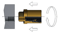
Screw the joint on the female threading seat. For a correct assembly of each joint follow the tightening coupling instructions given in table 1.
| THREAD | TIGHTENINGTORQUE (Nm) ± 10 |
|---|---|
| M 10 X 1 | 22 |
| M 12 X 1,5 | 24 |
| M 14 X 1,5 | 30 |
| M 16 X 1,5 | 35 |
| M 18 X 1,5 | 36 |
| M 22 X 1,5 | 40 |
| M 26 X 1,5 | 45 |
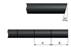
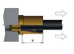
The pipe must be cut at a right angle or up to a maximum
of 15°. The coupling is correct only when the pipe reaches
the coupling value given in table 2.
If the pipe bears a
reference mark it must be cut exactly at that point.
| ØPIPE | DEPTH OF COUPLING (H) |
|---|---|
| 6 X 4 | 19,8 |
| 8 X 6 | 20,5 |
| 10 X 7 | 24 |
| 10 X 7,5 | 24 |
| 10 X 8 | 24 |
| 12 X 9 | 25 |
| 15 X 12 | 27 |
| 16 X 12 | 27 |
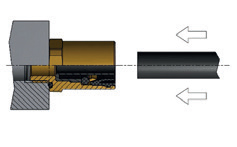
Insert the pipe into the joint rotating it slightly to ease the
insertion.
The pressure required to insert the pipe is given in table 3.
| Ø PIPE | FITTING FORCE (H) |
|---|---|
| 6 | 60 |
| 8 | 80 |
| 10 | 82 |
| 12 | 95 |
| 15 | 100 |
| 16 | 100 |
| 18 | 100 |
If there is a reference mark make sure the cut is flush with the joint. Pull on the pipe to make sure it is correctly fitted in.
Fraz. Roccapietra - Zona Industriale
Via Monte Rosa, 1
13019 VARALLO (VC)
![]() made in ITALY
made in ITALY